What’s up With Small-Scale Compressed Air Energy Storage?
Scalable, cheap energy storage is the last puzzle piece to complement the renewables revolution and finalize the global green energy transition. Plenty has been written and said about the incredible learning curve of battery energy storage systems, which are ushering in a new era of global energy distribution. Yet, alongside them, there are less prevalent and often overlooked forms of energy storage. When I recently compiled an overview of storage technologies, I got fascinated by compressed air energy storage (CAES) and now you have to hear about it, too. In fact, I think you should found a CAES company. But more on that below.
TL;DR:
CAES has been around for over a hundred years, driving everything from ventilation systems, cars, trains and elevators to underground energy storage. [Read more]
Large-scale CAES has significant advantages, most prominently a cheap levelized cost of storage due to decades-long plant lifetimes. Disadvantages include the dependence on suitable geology and the immense, bespoke planning and construction efforts required. [Read more]
Several companies are trying to overcome the limitations of traditional CAES, most importantly location restrictions and long deployment timelines. [Read more]
The success and favorable economics of large-scale CAES beg the question why we haven’t seen an explosion of small-scale, containerized CAES modules. [Read more]
I run through the technology and economics of a fictional 500 kWh CAES 40’ container energy storage. Back-of-the-envelope calculations seem to suggest that this type of product could be technologically feasible and economically superior to or at least on par with battery storage systems. [Read more]
Despite the promise of small-scale CAES, there seem to be only two companies actively working on this. Their traction and chances of success are unclear at this point. [Read more]
I. A Brief History of Hot Air
The idea of using compressed air to perform mechanical work is thousands of years old. It took many iterations to go from very primitive ancient bellows used for metallurgy to the first European hydraulic blowing machines in the late 1700s. Around 1800 the first industrial air compressors had been developed in the UK and with that the cat air was out of the bag (couldn’t help it, sorry). Compressed air was everywhere - first for ventilating coal mines, then for propelling cars and trains and later even for transporting energy across all of Paris:
 Steam-driven compressors in one of the power houses of the Paris Compressed Air Power Network. Source: The Manufacturer and builder, 1889.
Sidenote: The whole Paris Compressed Air Power Network is absolutely bonkers and completely fascinating. Although highly inefficient (because of thermal losses) it was in operation from 1879 until 1994(!) and for several decades rivaled the electricity network. The 1889 edition of the journal “The Manufacturer and builder” (which you should absolutely check out) describes the insane engineering and machinery that powered the network:
“The plant embraces twenty-two compressors: (a) Eight of the Sautter-Lemonnier type […] (b) Two compressors of the Casse type […] (c) twelve Blanchod compressors […] All these compressors together, take from the atmosphere more than half a million cubic meters of air per day, and distribute this medium throughout the city of Paris under a pressure of 6 kilograms (13.2 pounds), furnishing a motive power applicable for electric lighting, ventilation, running elevators, and for miscellaneous uses.”
Anyway, back to CAES. The 20th century saw decades of rapid innovation in the air compressor space, from the first oil-free reciprocating compressor to the invention of modern rotary screw compressors. Compressors became ubiquitous and started to power everything from refrigerators to pneumatic surgical tools. For a surpringly long time, compressed air was also still a popular choice for moving trains:
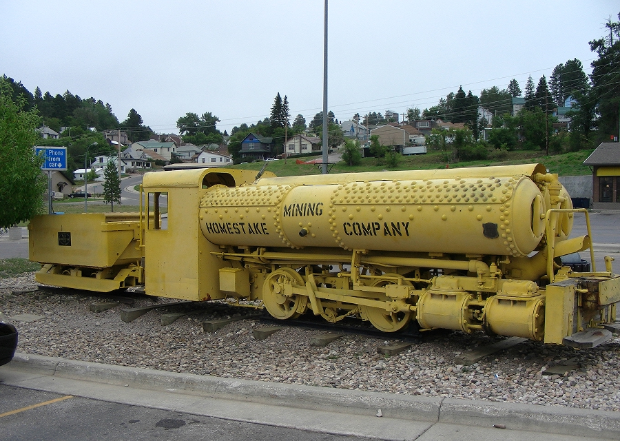 Compressed air locomotive in use at the Homestake Mine between 1928 and 1961. Photo by Wtshymanski on Wikipedia
In the late 1970s the idea of using compressed air in underground caverns as a large-scale energy storage for excess electricity was born. The first such plant commenced operation in 1978 in Huntorf, Germany and is still running today. It stores 480 MWh of electrical energy by compressing air into two salt caverns with a combined volume of 310,000 m³. Fully filling the caverns takes 8 hours, with a final storage pressure of 72 bar (1,044 psi).
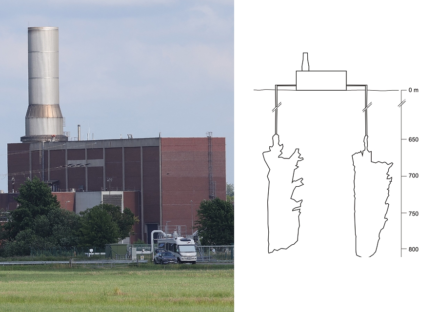 Left: The Huntorf CAES power plant (photo by KGF on Wikipedia).
Right: Schematic of the plant and the two caverns at the same scale (from Huntorf CAES)
The heat generated during compression is lost to the environment (diabatic process). To turn the stored energy back into electricity, that heat must be added again during decompression. This is done by burning natural gas in a gas turbine, whose compressor stage is driven by the air stream from the caverns. The plant has a total power of 321 MW and can release the stored energy for a total of 2 hours, after which the pressure is too low to support full-load operation. To release the 642 MWh of electrical energy, a whopping 960 MWh must be added from combustion of the natural gas, which itself requires a separate storage cavern. This yields a rather poor round-trip efficiency of 642 MWh / (480 MWh + 960 MWh) = 44.5%. While this is nowhere near the 70-80% effiency of, say, modern pumped hydro plants, Huntorf still provides useful backup capacity to the German power grid: The energy can be stored at very low cost (the caverns are already there) and once it’s needed, operation is significantly cheaper than running a pure gas peaker (as the compressor stage in the turbine is basically driven “for free” by the compressed air). A similar, 110 MW diabatic plant was opened in McIntosh, Alabama, in 1991.
From 2000 onwards several large-scale CAES facilities were built worldwide, some of them with capacities > 1 GWh. The newer plants (most of them built in China) all operate in an adiabatic fashion, meaning the compression heat is stored and re-used during decompression. They achieve round-trip efficiencies > 70%. Larger CAES plants always depend on the existence of suitable geological formations or storage reservoirs, such as salt caverns or abandoned mines.
II. What’s (Not) to Like?
Now that you know about the history, let’s briefly talk about the pros and cons of large-scale CAES:
👍 Pros
Scale: Because they use large underground reservoirs, traditional CAES plants can store energy on the order of hundreds or even thousands of MWh.
Lifetime: Once built, CAES facilities exhibit lifetimes of 40 years or longer. The Huntorf plant has been in operation for 47 years and has even been upgraded twice (more powerful turbine, higher storage pressure).
Storage duration: Diabatic plants can basically hold the energy for arbitrary amounts of time, as the compressed air simply sits in the caverns until its needed. Adiabatic plants have to deal with gradual loss of the stored heat, which - with modern thermal energy management - leads to storage durations of 10-100 hours.
No critical materials: CAES plants are made of standard turbomachinery components (steel, copper etc.) and thus have a much better environmental footprint than, say, lithium-ion batteries.
Low cost: Although the upfront investment for the plant, compressors, expanders etc. is comparatively high (>$150/kWh storage capacity), the long lifetime and falling price of renewable electricity mean that at ≥70% efficiency the levelized cost of storing and retrieving energy is competitive and converges to way below $0.10/kWh.
To understand the cost aspect, let’s run a very rough back-of-the-envelope calculation for the currently “world’s largest” CAES project, the Yingcheng energy storage station in Central China’s Hubei province. The facility sits on top of abandoned salt mines and provides 300 MW of power with an electrical storage capacity of 1,500 MWh.
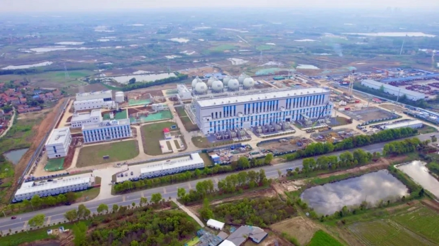 The Yingcheng energy storage station (Source: sasac.gov.cn)
According to official figures, the project was built within 2 years for a total cost of $270 million. It charges 498 GWh and outputs 319 GWh per year, which corresponds to a 64% round-trip efficiency and a charge-discharge cycle of roughly 2 days. Conservatively assuming a lifetime of 40 years and a solar LCOE of $30/MWh in 2025 which will linearly go down to $15/MWh in 2065, this would give us the following numbers:
| Plant investment (CapEx) | $270,000,000 |
| Lost energy per charge cycle (kWh) | 843,750 |
| Average cost of lost energy per charge cycle | $18,984 |
| Charge cycles across lifetime | 7,300 |
| Cost of lost energy across lifetime (OpEx) | $138,585,938 |
| Maintenance (OpEx) | $191,414,063 |
| Total cost across lifetime (CapEx + OpEx) | $600,000,000 |
| Total energy stored across lifetime (kWh) | 10,950,000,000 |
| Levelized cost of storage (LCOS) | $0.05/kWh |
Even though this is an oversimplified model and the charge cycles, electricity prices and maintenance costs may be different, you can see how the LCOS becomes incredibly cheap due to the long lifetime of the plant.
👎 Cons
Location-dependence: Large-scale CAES is geographically highly constrained because plants can only be built on top of suitable reservoirs like salt caverns or old mines. This puts a hard cap on the CAES capacity any given country can build out.
Maintenance: Though the plants have long lifetimes, they also have lots of moving parts and experience wear and tear in the compressor, expander, pipes etc. This makes continuous maintenance an obligatory annual cost on the order of 1-2% of the initial investment.
Bespoke megaprojects: The scale and geographic dependence of CAES means that every project has highly specific requirements and needs large amounts of bespoke engineering, procurement and construction (EPC) work. Though planning, permitting and construction can be 3-4 times faster than pumped hydro, projects are still endeavors in the tens or hundreds of millions of dollars and take several years to complete.
III. Next-Gen CAES
A number of companies have started to push the envelope of traditional CAES. Improvements include making CAES location-independent, more efficient, more modular and/or faster to deploy.
Highview Power 🇬🇧
Highview Power is a UK-based company that uses liquid air and sophisticated thermal management to provide long-duration energy storage in the hundreds and even thousands of MWh. Unlike other innovators in the space, they already have two large-scale projects under construction (300 MWh / 6h in Carrington, Manchester, UK and 3.2 GWh / 12.5h in Hunterston, North Ayrshire, UK) and several more in the pipeline.
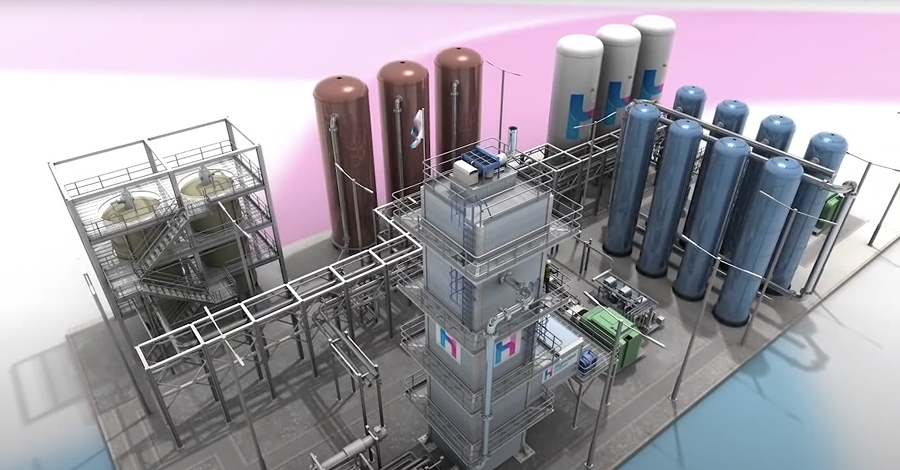 Source: Highview Power on YouTube
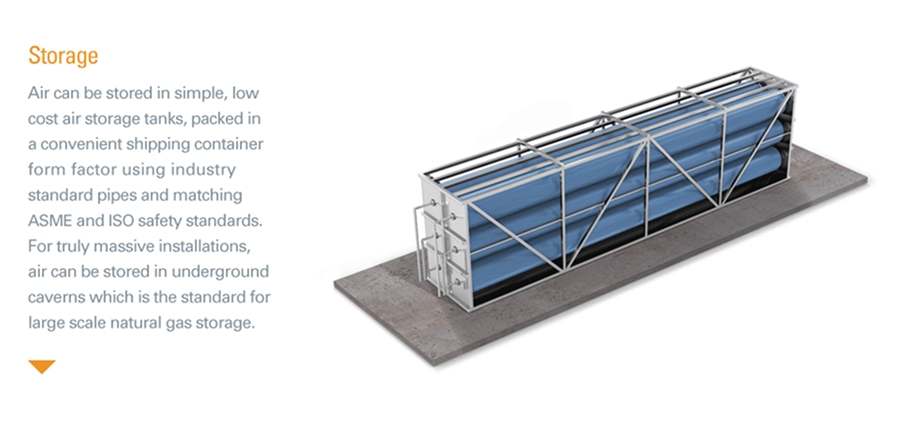
Highview removes the dependence on underground reservoirs by storing air in liquid form at -196°C and 1/700th its normal volume in onsite storage tanks. Waste heat and cold are stored in additional insulated tanks. When power is needed, the air is drawn from the tanks, pumped to high pressure and driven through a turbine. Highview uses proven components from the liquefaction and turbomachinery industry, claims a plant lifetime of >50 years and can supposedly realize a greenfield project within 2-3 years, from planning to completion.
Hydrostor 🇨🇦
Hydrostor is another large-scale provider of modern CAES. The Canadian company combines purpose-built underground hard rock caverns with separately constructed water heads into something they call “Advanced CAES” (A-CAES). This slightly loosens the dependence on natural geological caverns but still results in bespoke megaprojects. Their website lists two projects under “advanced development” (4,000 MWh / 8h in Willow Rock, California, USA and 1,600 MWh / 8h in Silver City, New South Wales, Australia) and several more in the pipeline. No concrete timeline for the completion of either of these projects is given. Like Highview, they claim a plant lifetime of >50 years.
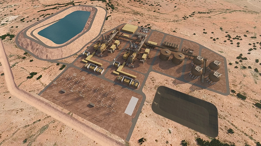 Source: Hydrostor website
While the size of these projects is impressive, overall timelines seem to be on the order of 10 years per project and - because of the intensive underground drilling, mining and geoengineering work - include several years of siting, feasibility studies, project development and permitting before construction can actually begin.
BaroMar 🇮🇱
BaroMar is an Isreali company that puts an interesting twist on CAES: Air storage vessels are located underwater, which creates favorable conditions for maintaining pressure. Target depths are 200 - 700 m, resulting in storage pressures of 20 - 70 bar (290 - 1,105 psi). BaroMar claims that the vessels require little to no maintenance and that the comparatively simple maritime deployment (as opposed to geological drilling) reduces installation costs to “as low as” $80/kWh.
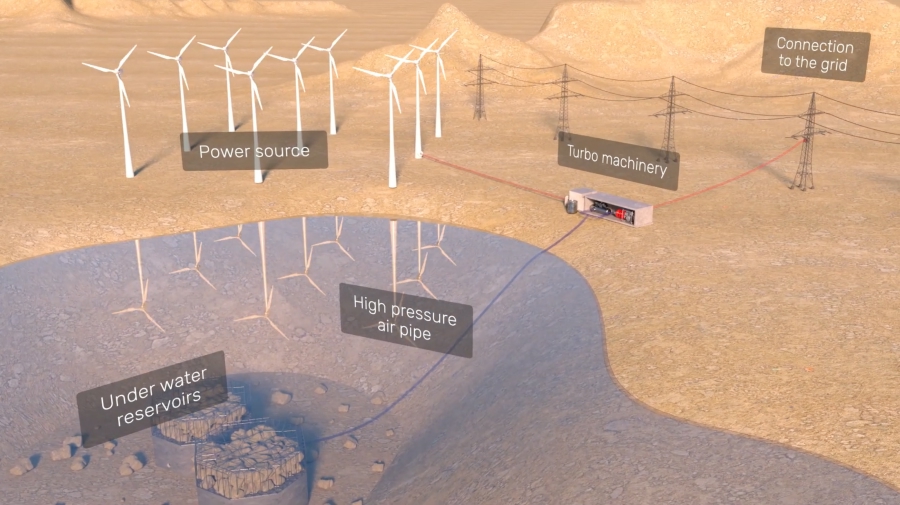 Source: BaroMar on YouTube
BaroMar seems to still be in the proof-of-concept phase, with a first 3 MWh / 10h demo project planned south of Cyprus. No concrete details on the plant or timeline are given.
SEGULA 🇫🇷
French engineering company SEGULA seems to have validated a similar idea to BaroMar’s proposition 9 years ago: REMORA was an innovation project funded by the French government that trialed “undersea CAES”:
 Source: REMORA project website
Although media coverage from 2020 claims that “first tests” confirmed the successful operation of a “land-based prototype”, there are no specs or concrete details beyond the 3D-rendered YouTube video and it seems that the project remains a showcase for SEGULA and various other engineering companies involved.
Augwind 🇮🇱
Israeli startup Augwind is combining compressed air with pumped water to create near-isothermal CAES. They still rely on underground caverns as a large-scale storage medium, but drive the air by means of turbomachinery and several large underground tanks that cycle water and air in reciprocating fashion (a.k.a. liquid piston mechanism). Augwind has a 1 MWh / 4h pilot plant running in southern Israel which demonstrated 47% round-trip efficiency in 2024 and is supposed to hit 60% in the future.
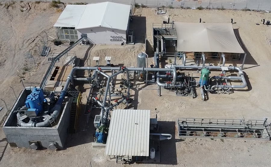 Source: Augwind website
It is unclear when Augwind’s tech will be available for real-world, large-scale storage projects, but the concept is detailed and the company is constructing and validating actual hardware in the field, which seems to put in on a good path forward.
Storelectric 🇬🇧
Storelectric is a UK-based company that tried to build momentum for traditional, cavern-based CAES and also proposed a somewhat vague combination of hydrogen and CAES as a storage solution. They have no concrete specs or demo plants on their website and - apart from a single proposed project for Teesside, UK - do not seem to have an actual project pipeline.
Others
There are many more companies operating in the CAES space. Notably, Siemens Energy is a large active player and so are various other tech conglomerates. I have not listed them above, because they often “only” provide the tried-and-tested turbomachinery components for CAES but do not plan and execute these projects themselves. Likewise, I have not listed the many specialized engineering firms that carry out the EPC work for new (and existing) CAES plants and buy and assemble the components from Siemens and others.
IV. Where Is My Small-Scale, Modular CAES?
Alright, we’re some 2,500 words into this post and you might ask: What’s your point, Klaas? Well, now that you have the context, let me get to it: CAES is a wonderful technology - it’s green (no critical materials), it’s durable (30-50-year lifetimes, yeah) and it’s cheap (if you can make the scale work). The thing that really bugs me, is: It is sooooo slow to deploy. The only company building actual, real-world projects at a scale and speed relevant for fighting climate change seems to be Highview Power.
I don’t blame these companies; they are trying to innovate and that’s hard. The main problem, in my opinion, is that too many of them are still betting on storing the air in some large underground reservoir. Your compression technology can be as innovative as you want - if your solution involves digging up the earth or diving to the bottom of the sea, you will end up with bespoke (mega)projects and have to go through multiple years of siting, permitting and plannning before a single compressor is deployed anywhere. The solution to this is “BYOV” - bring your own vessel. By using liquid air tanks (and a few other tricks) Highview Power seems to be the only innovator that has successfully removed the geographic restrictions and solved the large-scale CAES problem. Deploying hundreds or even thousands of MWh of storage within 2-3 years seems impactful.
But the question I keep asking myself is: What about small-scale, modular CAES? Is there a viable sweet spot where this could work out, both technologically and economically? Why can’t we deploy air storage systems in shipping containers, just like battery storage systems? If we could mass-produce these modules in factories, even with comparatively small storage capacities, surely we’d see some economies of scale? Wouldn’t we massively accelerate the rollout of global storage capacity if we could put these containers on every other solar farm? Wouldn’t we be way faster than just betting on a few, multi-year large-scale CAES projects? I will explore some of these questions in the following. Bear with me.
V. I Invented a Company
Today I am offering you a free idea for a company. Its name is Aerostor and it manufactures modular compressed air energy storage units. Here’s the title slide for our pitch deck:

The ™ is not real, I didn’t register the trademark. But you can, it’s not taken at the moment - go get it! You have my express permission to use the logo, too.
The Product
Of course, Aerostor needs a flagship product. How about a standalone 500 kWh / 4h CAES energy storage system that fits in a single 40’ shipping container? We’ll call it the Aerostor 500C40:
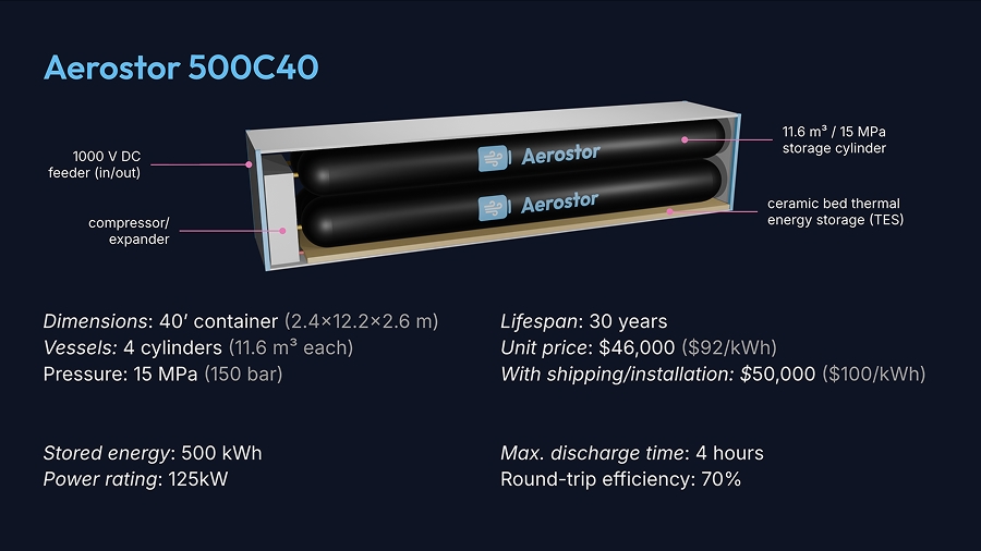
Before you ask: No, I did not make this up with AI. I actually fired up Blender to create a basic rendering of what I had in mind and put some thought into the specs. Let’s go through them:
The Physics
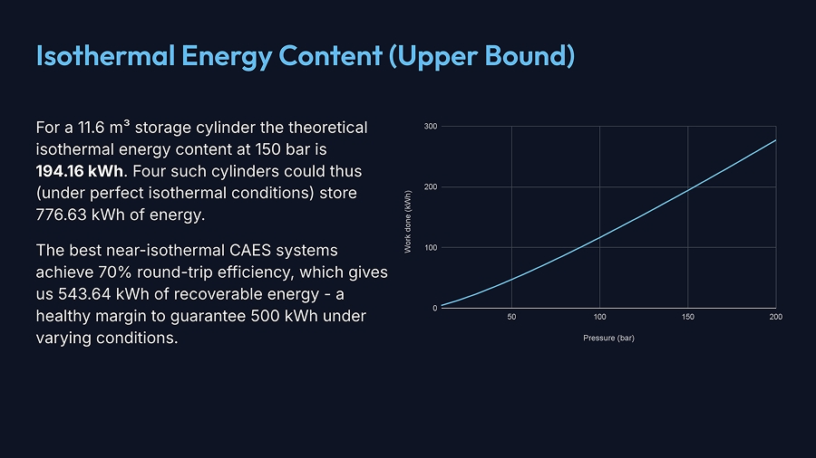
My primary design goal was to be able to store 500 kWh in a 40’ container. It turns out basic thermodynamics will give us pretty good guardrails on the necessary pressure and dimensions of the storage vessel. Let’s do a quick detour into physics land.
Let us, for now, assume that we can (somehow) keep the temperature constant during compression. The work done when compressing air from initial pressure and volume to target pressure and volume is then:
Now, since we’re drawing the air from the atmosphere, we don’t really know the exact initial volume. Fortunately, we can massage the formula a little to get rid of and end up with:
Next, the pressure outside the storage vessel is not zero but equal to the atmospheric pressure (which is our starting pressure ). This reduces the energy exploitable upon decompression by :
Note that we’re actually adding the term here as describes the work done during compression and that number is negative, because work is done on the gas by its surroundings. That’s right, to compress the gas, you “get negative energy out” which is another way of saying that you have to put energy in. When you decompress the gas you get that energy out. If we again rearrange the equation a bit, we end up with the final formula for the isothermal energy content of compressed air as
where is the volume of the storage vessel, is the atmospheric pressure and is the storage pressure. Nice! Go ahead and plug in some numbers. Be sure to use the SI units J(oule) for energy and Pa(scal) for pressure.
Now, realistically, we won’t be able to keep the temperature constant. Like all companies mentioned above, we’ll have to think long and hard about ways to store the waste heat from compression and and re-use it during expansion. If we do a really good job, we might call our system “near-isothermal”, otherwise we’ll just stick with “adiabatic”. For the purpose of our thought experiment it doesn’t really matter; we’ll assume that the Aerostor engineers have worked hard enough to achieve a best-in-class round-trip efficiency of 70%.
The Dimensions
Given the formula above, the assumption of 70% round-trip efficiency and a 40’ container, I started playing with numbers. The box needs some space for a compressor and a thermal storage bed (see below), but I decided that most of the space should (obviously) go to the storage cylinders. Four cylinders were a somewhat arbitrary choice; maybe it would be better to manufacture one huge cylinder or to use 12-16 standardized smaller cylinders. Four seemed like a good start and the cylinders shown in the slide above have a length of 11 m and a radius of 0.59 m, leading to a storage volume of = 11.6 m³ per cylinder. Iterating through different possible pressures, I arrived at the following conclusion:
Alright, 150 bar (2,176 psi) it is. This may seem like a lot, but it’s actually on par with the pressure used to transport natural gas (up to 200 bar) in pipelines of similar diameter.
The Compressor / Expander
We have the storage cylinders, now what about the other components? For one thing, we will need a powerful compressor and expander, ideally contained in one unit. There are two options for this: So-called “expander-compressors”, sometimes just referred to as “turboexpanders”, are machines that have a common shaft and house a centrifugal expander wheel on one end and a centrifugal compressor wheel on the opposite end. The problem is that these are usually large, expensive pieces of machinery that drive several MW of power. We need something more compact. The other option, then, is to use a compressor that can act as an expander when run in reverse. Only certain types of compressors with specific geometries are suitable for this. The ones I found are:
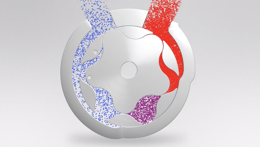
Twin‑screw compressors: This type of compressor has been thoroughly studied in the context of refrigeration systems and been shown to efficiently compress and expand gases. A 2002 paper on the subject explains the compressor as follows: “Screw compressors are positive displacement rotary machines which essentially consist of a pair of meshing helical lobed rotors contained in a casing. Together, these form a series of working chambers […] The dark shaded portions show the enclosed region where […] compression takes place, while the light shaded areas show the regions of the rotors which are exposed to external pressure.”
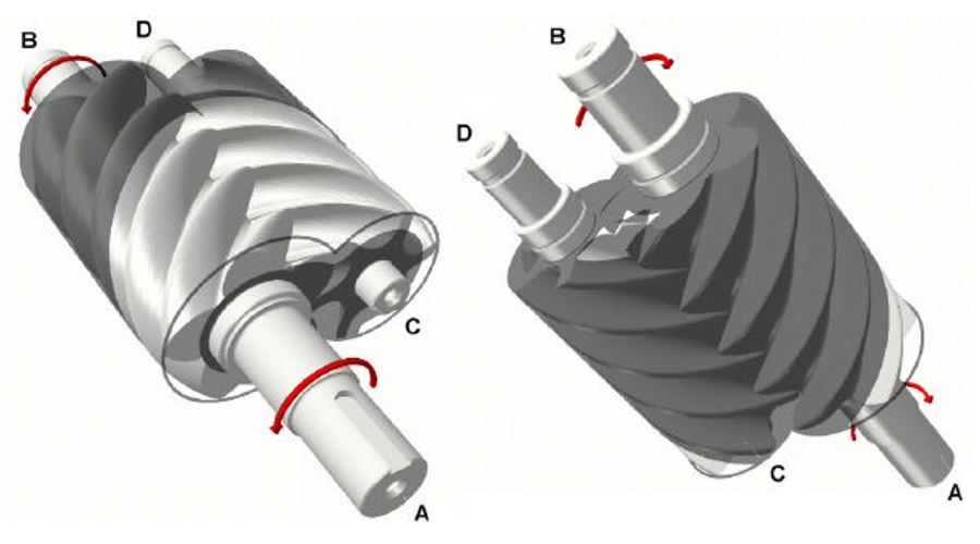 Source: A Twin Screw Combined Compressor And Expander For CO2 Refrigeration Systems
Twin-screw compressors can smoothly be run in reverse to act as expanders.
Scroll compressors: This type of compressor is most commonly used in air conditioning systems. It essentially traps the air inside two interlocking spirals. The inner spiral moves on a circular path (without rotation) and forces the air further towards the middle, where it has less room and is thus compressed. Here’s a nice animation of the working principle:
 Animation by Cacycle on Wikipedia
Fun fact: I once tried (and failed) to 3D-print a scroll compressor … that’s a story for another day, but as a left-over from that experiment I do have a nice cutaway rendering of the interlocked scrolls for you (inner scroll in green, the compressed air goes out through the top duct):
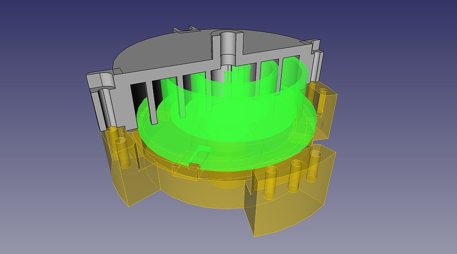
Scroll compressors are known to operate smoothly, quietly and reliably and can easily be run in reverse to function as scroll expanders.
Specialized positive‑displacement compressors: There are other geometries that will compress air when rotated, some of them pretty ingenious. For example, this star-shaped rotor efficiently and smoothly compresses gas in a continuous motion:
 Source: StarRotor website
The beauty of designs like this is that they operate equally well in either direction (compression or expansion) and are efficient at small-scale (in the kW range) and at varying rotor speeds.
We won’t pick a specific compressor type here, but make a note that the box titled “compressor/expander” in the slide above will contain a compact, powerful and reversible compressor with as few moving parts as possible to maximize durability and minimize maintenance. We trust that the Aerostor engineers will find the best compressor/expander design that satisfies these requirements while allowing for the target round-trip efficiency of 70%.
The Thermal Energy Storage
Designing thermal storage is difficult and beyond the scope of this post, but let’s at least work out some rough numbers. During isothermal compression, most of the work turns into heat that we have to store somewhere. As a first approximation, let’s assume our thermal energy storage (TES) must be able to hold the full 500 kWh worth of heat.
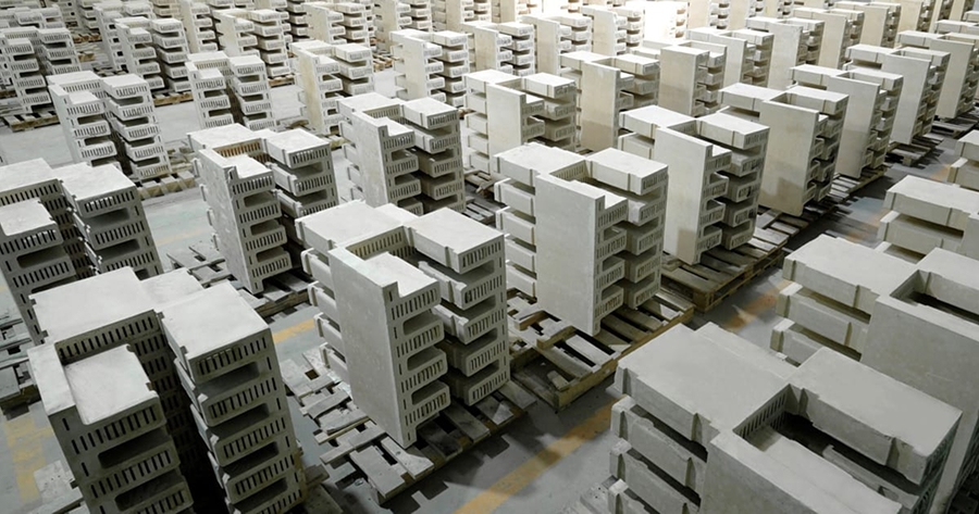 Stacks of fireclay bricks used in Rondo Energy’s heat battery (© Rondo Energy)
Existing solutions in the TES space often use ceramic materials like bricks or simply heaps of sand to store heat for long periods of time. Let’s assume the space below the four cylinders is fully filled with insulated flat bricks for a total volume of approximately = 3.5 m³. A matrix of aluminum or steel intercoolers enables the seamless transfer of heat between the cylinders and the bricks. How hot would the bricks get if heated with = 500 kWh (1,800 MJ)?
Typical fireclay bricks have a specific heat capacity of around = 1,000 J/kgK and a density of = 1,500 kg/m³, which would result in a temperature rise of:
Hmm, a 340°C increase (around 650°F) seems pretty hot, I’m not sure we would want to put a mass that hot underneath our cylinders. But we have wiggle room. We could slightly reduce the cylinder size and increase the storage pressure, which would give us the same storage capacity while allowing for a larger TES block. Or we could use the High Cube container format for additional height. If we manage to make room for 8 m³, this would raise the brick temperature by = 1,800 MJ / (1,500 kg/m³ · 8 m³ · 1,000 J/kgK) = 150 °C. That seems pretty acceptable. Alternatively, we could use a storage medium with a higher specific heat capacity. Water, for example, can store about 4 times as much energy per unit volume as brick. However, using liquids would likely introduce a bunch of additional cost and complexity (tanks, valves etc.) that’s unlikely to fit in the box. For now, let’s stick with tried-and-tested fireclay which is cheap ($150/t at large volumes), has great heat retention properties and is abundantly available.
In summary, our container will house a 6-8 m³ block of insulated ceramic thermal energy storage and a bunch of aluminum or steel intercoolers.
The Costs
Let’s skip the other small components (power electronics, racking, casing) and talk money. A bit of research confirmed that tanks are expensive. We’re gonna need 4 large steel tanks and they seem impossible to procure for less than $5,000 a piece. Ouch. For the compressor/expander I had a hard time finding reliable quotes. In the 50-150 kW range, prices vary from several thousand dollars to 6 figures. Let’s assume that Aerostor’s R&D will result in an ingenious, mass-manufacturable compressor/expander design that will run us only $9,000 (optimistic but let’s roll with it). Shipping containers should be doable at ~$3,000 (we could even start with used ones). The TES block will run us ~$1,500 for the ceramic bricks and another $500 for intercooler pipes. The remaining components are best guesses and factory assembly remains significant for now, but should go below $1,000 in the long run.
| Component | Price | Qty | Total |
|---|---|---|---|
| Storage cylinder (11.6m³, 150bar, steel) | $5,000 | 4 | $20,000 |
| Compressor/expander unit (15 MPa, 125 kW) | $9,000 | 1 | $9,000 |
| Container (40’) | $3,000 | 1 | $3,000 |
| Ceramic thermal bed + intercoolers | $2,000 | 1 | $2,000 |
| Racking, pipes, fittings | $800 | 1 | $800 |
| Power electronics, SCADA | $1,000 | 1 | $1,000 |
| Assembly, QA | $1,000 | 1 | $1,000 |
| Product cost | $36,800 | ||
| Margin (20%) | $8,000 | 1 | $9,200 |
| Shipping & installation | $4,000 | 1 | $4,000 |
| Total | $50,000 | ||
A lot of these assumptions are aggressively optimistic, I know. Also, 20% is at the lower end of what you would want to earn as a hardware-producing company. But before you pick apart the line items, let’s look at the per-kWh price for a second: For the 500 kWh system we land at $100/kWh for the installed cost. That’s not bad. Consider the 2025 installed cost of 4-hour lithium-ion battery energy storage systems (BESS) and its projection until 2050:
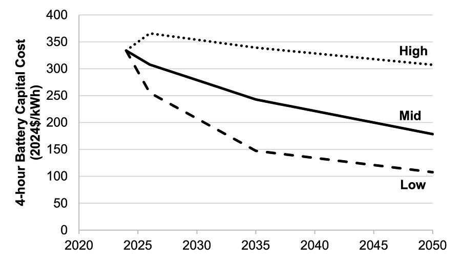 Battery cost projections for 4-hour lithium-ion systems (Source: NREL 2025 Update)
Even though the NREL numbers are from Feb 2025 and lithium-ion batteries have seen accelerated price decreases since then, the CapEx of fully installed BESS will likely stay north of $100/kWh for many years to come. But it gets better: The CAES components we use for the Aerostor unit (compressor, tanks, ceramic bed) easily warrant lifetimes of 30+ years. This is in contrast to a typical BESS lifetime of 10-15 years, where battery cells degrade irreversibly after a few thousand charge/discharge cycles. When paired with solar arrays, this means that a battery energy storage system would have to be replaced at least once, while compressed air energy storage could - with proper maintenance - match the 30-year lifespan of the solar panels. It is hard to overstate how positively this affects the overall economics.
The Unit Economics
Let’s run a simplified side-by-side comparison of our fictional Aerostor battery with a state-of-the art 500 kWh lithium-ion storage system. We’ll assume daily charging and discharging from co-located solar panels with a solar LCOE of $30/MWh. In our vision, the Aerostor 500C40 will be commercially available for $50,000 in 2030, at which point BESS will cost $280/kWh according to the “Mid” projection shown above (both costs “fully installed”). To make full use of the 30-year solar panel lifespan, the BESS will need to be replaced with a new system after 15 years, then costing $200/kWh.
| BESS | Aerostor | |
|---|---|---|
| Storage capacity (kWh) | 500 | 500 |
| Size (container) | 20’ | 40’ |
| Lifetime (years) | 15 | 30 |
| Round-trip efficiency | 90% | 70% |
| Cost of installed hardware (CapEx) | $140,000 | $50,000 |
| Cost of replacements across 30 years (CapEx) | $100,000 | $12,000 |
| Lost energy per charge cycle (kWh) | 55.6 | 214.3 |
| Cost of lost energy per charge cycle | $1.67 | $6.43 |
| Charge cycles across 30 years | 10,950 | 10,950 |
| Cost of lost energy across 30 years (OpEx) | $18,250 | $70,393 |
| Maintenance (OpEx) | $21,000 | $7.500 |
| Total cost across 30 years (CapEx + OpEx) | $279,250 | $139,893 |
| Total energy stored across 30 years (kWh) | 5,475,000 | 5,475,000 |
| Levelized cost of storage (LCOS) | $0.051/kWh | $0.026/kWh |
Despite its lower efficiency, the long equipment lifetime causes the CAES solution to perform significantly better, with an LCOS almost 2x cheaper than battery-based storage. Of course, all of this is theoretical and based on optimistic assumptions. We’d have to prove that the engineering and manufacturing side works out, that components can be mass-procured and storage units be mass-produced at these prices, that daily charging/discharging works reliably, that the chosen materials can withstand the wear and tear of high pressure and temperature changes over 30 years etc.
But still, none of this is rocket science; what’s required is engineering and manufacturing excellence. The types of components needed by the Aerostor system have been in use in turbomachinery, heat & power and heavy industry applications for decades. It’s about refining their design and integrating them in such a way that they perform air compression/expansion cycles with maximal efficiency, minimal heat loss and minimal maintenance. And there is plenty of room (and cost buffer) in the design space. Think the TES will need to be bigger? Make the cylinders smaller and the target pressure higher. Need a more powerful compressor for that? Better power electronics? Have at it. We can probably add up to 50% additional cost and the Aerostor would still be a worthwhile investment, as long as it’s reliable and long-lived.
Variations
Higher pressure
What if we used a 20’ container but much higher pressures, say 500 bar (7,252 psi)? We probably couldn’t use steel tanks for this, but carbon fiber reinforced polymer (CFRP) might work. The tanks would be more expensive to make, but the higher pressure would mean that we can store 1 MWh (or more) instead of 500 kWh.
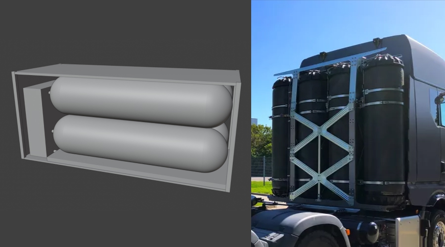 Left: 20’ Aerostor configuration with smaller cylinders. Right: Four Voith H₂ tanks behind a semi-trailer cabin (© Voith).
The nice thing about CFRP tanks is that they are becoming proliferant in the context of hydrogen-powered long-haul trucking. For example, tanks manufactured by German automotive supplier Voith are rated for a pressure of 700(!) bar and fulfill the highest safety standards, as four of these tanks sit right behind the driver cabin.
Multiple units
What if we combined multiple Aerostor 500C40 units to obtain several megawatt-hours of storage? Obviously this is the idea behind modular containers and if the goal is maximum redundancy this configuration is fine. But if we place, say, 8 containers on a given site, it seems suboptimal to deploy 8 semi-powerful compressors and 8 small(ish) thermal beds along with the cylinders. Maybe, for this scenario, Aerostor could offer other products, like 6 “pure storage” containers with cylinders only, one container with a large, powerful compressor/expander and one container with dedicated thermal storage. Intercoolers would have to run between these containers, so deployment and installation would be a bit more involved.
Someone Should Build This Company
Alright, enough exploration. In principle, I believe both the technology and the economics of Aerostor make a promising case for small-scale CAES. The specific challenges Aerostor would have to solve are:
Machinery: Design and manufacture the best reversible 100-250 kW compressor/expander unit on the market or partner with specialized manufacturers that have the know-how. Focus on performance, reliability and long lifetime with few components, ideally lubricated for life.
Tanks: Figure out a scalable way to procure large, robust storage tanks at minimal prices. If it has to be steel, build dedicated supply chains for custom-made tanks, e.g. in Asia. If it ends up being CFRP, find a strong local manufacturing partner and secure production capacity.
Safety: The Aerostor units must be marketed and deployed with rigorous safety guarantees. Even though people are close to pressurized gas and fuel tanks all the time, there will likely be fears of storage vessel explosion (check out this entertaining Mythbusters’ episode). The risk of explosion (e.g. due to leaks or hull ruptures) must be detected and mitigated as early and effectively as possible to guarantee “walkaway safety”. This is similar to modern battery storage systems, which aim to detect and prevent fires/explosions caused by thermal runaway in the highly flammable lithium-ion cells.
Longevity: To win the trust of customers, Aerostor will have to give long warranties on its equipment, which in turn requires rock-solid confidence in the durability of its components, the engineering work with which they were integrated and the QA performed on each sold unit.
Scalability: The Aerostor idea will only work out (commercially and from a climate impact perspective) if the goal is to eventually deploy hundreds of thousands of units. From the very first prototype, the focus should not just be on the storage unit itself, but also on the scalability of the manufacturing process (“the machine that builds the machine”).
Alas, I lack the hardware engineering and manufacturing expertise to build this. If you come from a MechEng or aerospace background, if you’re mechanically intuitive and like building stuff with pressure, heat and rotating machines, if you have expertise in industrial manufacturing … you should absolutely build this company!
How cool would it be if from 2030 onward solar farms were accompanied by a few innocuous-looking containers that provide megawatt-hours of integrated storage for the lifetime of the farm, no lithium required?
If Aerostor finds its footing in the global market and sells 300,000 units by 2040, that would be at least 150 GWh of storage deployed. A significant dent in the green energy universe.
VI. Isn’t Someone Doing This?
If small-scale CAES is such a good idea, surely someone must already be working on this, right? I found a total of three companies. One of them is long dead, the other two still exist, with unclear progress and traction.
Lightsail Energy 🇺🇸
Founded in 2008, Lightsail was a Silicon valley darling that attracted star investors like Khosla Ventures, Peter Thiel and Bill Gates. By 2016 they had raised a whopping $70 million in VC funding. After some initial pivoting, their goal was to provide CAES in shipping containers. The company focused on achieving near-isothermal compression by spraying water into the storage vessel during compression (a known technique). They also explored ways to efficiently manufacture CFRP tanks.
 A slide from Lightsail’s 2012 pitch (© Lightsail Energy, Source: WattNow).
Lightsail’s first storage product was supposed to ship in late 2013 but never saw the light of day. The company ultimately failed to produce anything other than a few storage tanks, which were sold off to natural gas companies when it shut down.
Keep Energy Systems 🇬🇧
Keep (formerly Cheesecake Energy), founded in 2016, is a UK-based spin-out from the University of Nottingham that repurposes old truck engines to store energy in the form of heat and pressure. Their solution is containerized and makes use of small vertical pressure tanks as well as (what looks like) a sand-based TES. The containers seem to have a comparatively small footprint, but do require external pipe connections and storage tanks. The company claims 65% round-trip efficiency and a lifetime of 25 years. There is no mention of the pressure and/or storage capacity of the modules.
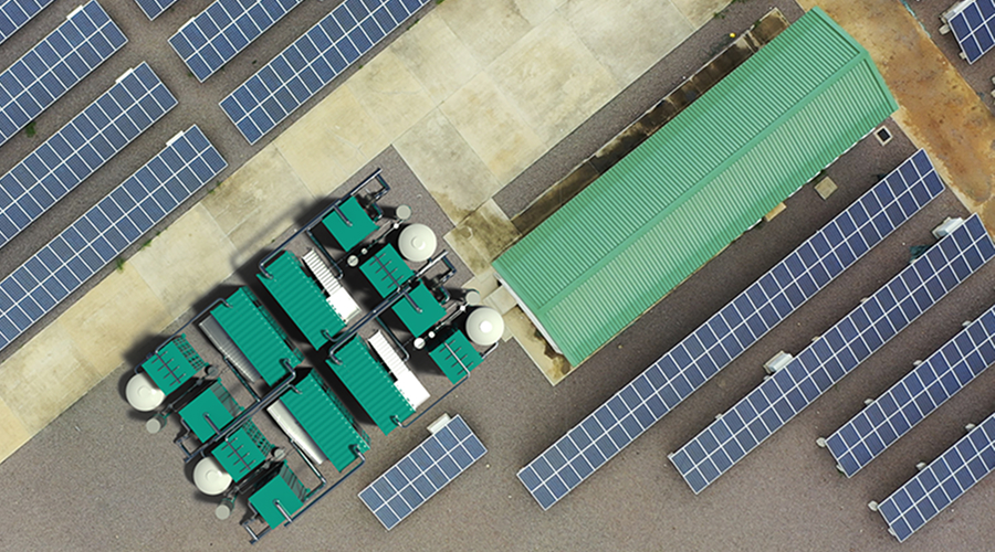 Top view of Keep’s storage system co-located with a solar farm (© Keep Energy Systems).
Keep’s new website briefly mentions a functional prototype system in Nottingham, UK, and some pilot opportunities, but has no details on active deployments or a project pipeline. This is surprising, as the old website (and several news sites) announced a £9.4m government grant for Keep (then still Cheesecake) to “install a set of pilot energy storage systems in Colchester”. It is unclear what happened to the Colchester project - if it’s still ongoing, I would have expected it to be listed as the first “real-world” deployment on Keep’s website.
Although Keep’s concept, system renderings and product presentation appear detailed and convincing, my impression is that they are stuck in the piloting stage and not yet ready for a commercial rollout anytime soon.
SEGULA (again) 🇫🇷
Surprise! The French engineers that came up with undersea CAES are now bringing you … CAES on land. REMORA Stack is touted as a “large-scale renewable energy storage” solution that supposedly achieves isothermal compression. From the March 2025 product announcement:
“REMORA Stack is a modular solution using 40-foot containers installed outdoors, aimed mainly at sites with a need for energy autonomy: industrial sites, production sites, eco-neighbourhoods, shopping centres, renewable energy parks, etc. It is a non-polluting, efficient (70% efficiency) and environmentally responsible solution thanks to the use of robust and standard technologies that give it a lifespan of at least 30 years.”
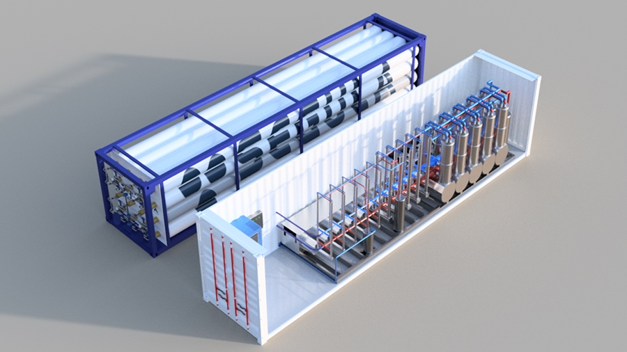 REMORA Stack product rendering (© SEGULA Technologies)
The announced specs certainly tick all the right boxes: 70% efficiency would be best-in-class for small-scale CAES. A 30+ year lifetime unlocks the massive economic benefits outlined above. The 3D rendering shows a distributed setup with 16 slim (possibly standardized) storage cylinders in one container and the TES and compressor/expander in another. As discussed above this makes sense, especially when deploying larger amounts of storage.
SEGULA seems to be partnering with ABC Compressors for the compression/expansion hardware. The development is funded through the Air4NRG EU project (gotta love these project names ;-). A PR announcement from March 2025 says that the “first industrial-scale pilot is scheduled for 2026, with the first production units to be rolled out in 2028-2029”. That sounds ambitious but generally doable.
I can’t really tell how serious SEGULA is about this. The EU project website has the usual slew of generic workshop and meeting updates. Although SEGULA’s product announcement and timeline seem concrete and ambitious, I have my doubts whether this will become more than a cool technology showcase. At its core, SEGULA is a multinational engineering services provider, developing and deploying solutions in vastly different areas, from aerospace & defence to life sciences and rail technology. They certainly have the engineering chops to design and prototype a working, containerized CAES solution. But to actually bring this to market at mass scale, compete with the rapidly growing BESS segment and make a difference on the climate front will require large capital investment and the willingness to take on significant entrepreneurial risk. I am rooting for SEGULA and seriously hope they can make this work.
Closing Thoughts
This turned into quite the deep dive… I hope you had fun exploring some of the CAES specifics with me. In my opinion air compression is and remains a highly fascinating and competetive technology. The future is electric and batteries will capture the overwhelming majority of the storage market, for sure. But this vision of having long-lived, “Jules Vernes”-like machines provide reliable, containerized energy storage without having to dig up rare earth materials is somehow deeply appealing to me, partly for its steampunk aesthetics and partly because it feels more sustainable and economically prudent.
And who knows, maybe you will lead Aerostor™ to become the #1 global modular CAES solution it deserves to be ;-).
PS: As always, if you have thoughts or doubts around any of the topics discussed above (physics, tech, economics etc.), please let me know in the comments below. If you enjoyed reading this, consider subscribing to future posts via the RSS feed below.